
| Photoiupac home page | Discussion | Photobiology.com home |
Stefan H. Bossmann,a* Claudia Turro,b Claudia Schnabel,a Megh Raj Pokhrel,a Katharine Janik,a Michael Wörner a
aLehrstuhl für Umweltmesstechnik, Universität Karlsruhe, 76128 Karlsruhe, Germany
bDepartment of Chemistry, The Ohio State University, Columbus, OH 43210, USA
Abstract. Novel heterogeneous photocatalysts were developed that are able to transfer electrons from excited Ru(II) donors within the zeolite framework to Co(III) acceptor complexes in the exterior. The materials were prepared and characterized by elemental analysis, electrochemical methods, diffuse reflectance, and raster and transmission electron microscopy. The catalysts consist of zeolite Y-encapsulated Ru(bpy)32+ (bpy = 2,2´-bipyridine) sensitizers in close proximity to TiO2 nanoparticles on the same support. The photophysical properties of Ru(bpy)32+ within the zeolite supercages were investigated at different loadings of Ru(bpy)32+ and TiO2. The photoexcited MLCT state of the zeolite-entrapped Ru(bpy)32+ reacts via electron transfer with Co(dpphen)33+ (dpphen = 4,7-diphenyl-1,10-phenanthroline) in the exterior of the zeolite particles. The relative quenching of Ru(bpy)32+ by external Co(dpphen)33+ increases as the TiO2 content within the zeolite is increased, where electron transfer from Ru(bpy)32+ complexes within the interior of the zeolite are able to transfer electrons to Co(dpphen)33+. This observation indicates that electrons can be transported from the interior of the zeolite to the surface in the presence of an appropriate electron relay, such as TiO2 nanoparticles.
Introduction
The need to remove highly toxic compounds from potential sources of drinking water with efficient catalytic materials is of profound importance at the present time. Thermal catalysts have been intensely investigated for this purpose, however, the reaction rates of such systems are slow compared to those possible with photoactivation. An advantage of photocatalysts is their reactivity at various temperatures, including 25°C, whereas thermal catalysts typically require high temperature for operation. In addition, light-activated catalysts can be easily turned "on" or "off" in the presence or absence of a photon source, respectively. More efficient photocatalysts that operate with visible light are necessary to improve cost efficiency, to utilize solar energy, and to avoid the formation of highly toxic side products, such as dioxins, dibenzofurans, and polychlorinated hydrocarbons. An ultimate future goal of this work is the development of highly efficient heterogeneous photocatalysts for the decomposition of xenobiotics.
Experimental Section
General Procedures. All reagents and solvents used were of the highest purity available and were purchased from Aldrich and Fluka. H2O possessed tridest. quality (UHQ-II). Co(dphen)33+ (dpphen = 4,7-diphenyl-1,10-phenanthroline) was prepared by a procedure previously reported. X-ray powder diffractograms were recorded at the institute for mineralogy at the University of Karlsruhe (Prof. E. Althaus). Raster electron microscopy was performed in the laboratories for electron microscopy at the University of Karlsruhe (Prof. D. Gerthsen). For quantitative HPLC analysis an HP Series II 1090 Liquid Chromatograph, equipped with a diode array detector and a LiChrospher-100 RP 18 column and precolumn was used, where the mobile phase was 0.10 M (C2H5)3N / H3PO4 (pH=7.0) and acetonitrile (65:35 v/v). TOC was measured by means of an Dohrmann DC-190 analyzer. We thank FISONS for elementary analysis (ICP/MS).
The program "IMAGE" was utilized (developed by the National Institute of Health, USA) for the analysis of the results of the raster electron microscopy. The program is able to identify and count particles of different size (TiO2-surface-nanoparticles and zeolite Y particles). Several in-house macros were written, which identified the size distribution of the TiO2 particles. Using the size, the number per zeolite Y particle, and the average density of the TiO2 particles (d 1.2 g cm-3), we were able to estimate their amount on the surface of the zeolite.
All electrochemical experiments were performed using a computer controlled EG&G Princeton Applied Research Potentiostat/Galvanostat (Model 263A) and the EG&G M270 software. Ru(bpy)3Cl2/Ru(bpy)3(ClO4)2 was used as an electrochemical standard. Cyclic voltammograms and Differential Pulse Voltamograms (DPV, 50 mV pulse height) of the standard complex were taken using a glassy carbon working electrode vs SSCE reference electrode (sodium saturted calomel electrode), and a platinum sheet auxiliary electrode. For the measurements of the redox potentials of the Ru(bpy)32+/TiO2 - codoped zeolites, a working electrode was constructed from a mixture of 200 mg carbon paste (Metrohm) and 100 mg of doped or codoped zeolite powder. This mixture was pressed on both sides of a 15 mm x 15 mm gold grid. After immersion of this working electrode into 0.50 M Na2SO4 in water the measurements were recorded (without ohmic drop correction). In control experiments, electrochemical signals due to the undoped zeolite Y composite electrode were identified.
Steady-state and time-resolved fluorescence measurements were performed using an Edinburgh Analytical Instruments (EAI-FS/FL900) Single-Photon-Counting instrument, which is able to fit lifetimes in the range of 500 ps to 500 ms. For these experiments 10 mg of the zeolite samples were predried for 12 h at 100°C, then 3.0 ml H2O was added prior to each measurement. For the quenching experiments a Co(dpphen)33+ stock solution was prepared in EtOH (0.1 mM) and added stepwise to the zeolite suspension containing the encapsulated luminescent *Ru(bpy)32+ complex. Control experiments show that mixtures of various solvents with water, including ethanol, did not result in emission quenching of the Ru(bpy)32+ encapsulated within the zeolite.
 Results and Discussion
Synthesis of the Ru(bpy)32+-Containing Zeolite Y
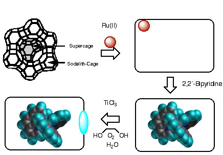
Ru(bpy)32+-Doped Zeolite Y. Zeolite Y belongs to the faujasite family and is composed of tetrahedral SiO4 and AlO4- building blocks which form six-membered rings. The combination of four- and six-membered rings leads to the formation of large cavities, the b-cages. Zeolite Y, with chemical formula H500Na56Al56Si136O634, contains eight large cavities per unit cell. These supercages with diameter ~1.30 nm are connected to each other by tunnels or "windows" of widest diameter ~0.74 nm. The ratio of cavities to windows in the interior of zeolite Y is 1:3.
Since Ru(bpy)32+ has a diameter of 1.08 nm, its synthesis must be performed using a "ship in a bottle" technique where the supercages of the zeolite Y are doped with Ru3+ and subsequently, the ligand 2,2´-bipyridine is added through the windows of the zeolite structure. The Ru3+/Na+ ion exchange was performed in NH3/H2O (30 % per weight), using RuCl3 as the ruthenium source. Refluxing in NH3/H2O results in a change in color from black to reddish-pink, which is indicative of the reduction of Ru(III) to Ru(II). During this reaction, the Ru(II) complexes Ru(NH3)6-n-m(H2O)n(AlO-)m2-m are formed, and are stabilized by the AlO- groups of the zeolite which serve as the starting material for ligand exchange reactions with 2,2´-bipyridine. Whereas previous procedures for the synthesis of Ru(bpy)32+ within the zeolite cavities attempted to optimize the reaction by varying the temperature, we dispersed the zeolite Y particles in appropriate solvents allowing definition of the precise reaction temperature by their boiling temperatures under normal pressure. This experimental procedure also results in the best reproducibility and provides increased solubility of the ligand, thus permitting its equal distribution among the zeolite particles. In refluxing ethanol (bp = 78°C) Ru(NH3)2(bpy)22+ is formed, whereas in boiling ethylene glycol (bp = 196°C) Ru(bpy)32+ is prepared with very good yields (80 - 95%). For technical reasons (filtration, recycling of the photocatalysts) relatively large zeolite particles were employed with an average diameter of 1.0 x 10⁻⁶ m and an average number of cavities per particle of 5 ± 2 x 10⁸.
TiO2 Nanoparticles in Ru(bpy)32+-Doped Zeolite Y. The procedure for the synthesis of TiO2 nanoparticles within zeolites consists of several steps shown in Scheme 1. The initial cation exchange process is conducted with TiCl3 as the titanium source and ethylene glycol as the solvent. An argon atmosphere is imperative because of the risk of explosion if only traces of oxygen are present! The hydrolysis of the titanium(III)chloride on the zeolite particles was carried out at -5 to 0 °C, followed by the oxidation of the Ti(III)/Ti(IV) clusters with air and treatment at high temperature (150 °C) to obtain well defined Ti(IV) nanoparticles.
Characterization of the Ru(bpy)32+/TiO2-codoped
Zeolite Y Materials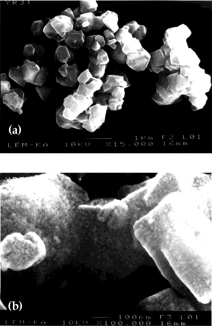
X-Ray Powder Diffraction. The novel Ru(bpy)32+/TiO2 co-doped zeolite photocatalysts were characterized by X-ray powder diffraction. All spectra obtained were consistent with literature reports on zeolite Y. No experimental evidence of the X-ray pattern for crystalline Ru(NH3)62+, Ru(bpy)32+, or crystalline TiO2 embedded in the zeolite Y structure is available. From the X-ray powder diffraction pattern it may be concluded that neither the incorporation of Ru(bpy)32+ nor the subsequent incorporation of TiO2 change the framework of the host (zeolite Y) significantly. The cavity of zeolite Y is considerably larger (d = 1.38 nm) than the diameter of Ru(bpy)32+ (d = 1.08 nm), thus permitting many locations and orientations of the ruthenium complex within the zeolite Y cavity. Therefore, no X-ray pattern arising from encapsulated Ru(bpy)32+ was observed. The powder diffraction data is not consistent with the presence of any crystalline TiO2, therefore we conclude that amorphous TiO2 (nano)particles are formed inside and/or on the outside of the zeolite particles.
Raster Electron Microscopy. The structures of the Ru(bpy)32+-doped zeolite Y and Ru(bpy)32+/TiO2 codoped photocatalysts reported in Table 1 were investigated using raster electron microscopy. The images presented in Figure 1 are typical for all zeolite-Y-based photocatalysts synthesized in this work, and exhibit a smooth surface of the heterogeneous Ru(bpy)32+-doped zeolite Y (Figure 1a). It is clear from the image that the structure of zeolite Y has not changed during the doping with Ru(bpy)32+. However, upon treating the Ru(bpy)32+-doped zeolite Y with TiCl3, the surface of the photocatalysts undergoes a remarkable change. After the TiO2 doping procedure, nanoscopic TiO2-particles are present at the surface (Figure 1b). Their average diameter was determined to be in the 1 x 10⁻⁹ to 5 x 10⁻⁹ m range. A computer assisted analysis of the images using the program IMAGE led to the estimation that approximately 20% of the TiO2 is located at the surface of the particles, therefore 80% of the TiO2 is embedded within the zeolite framework. According to the geometric features of zeolite Y and to the experimental fact that most of the cavities are filled with one Ru(bpy)32+, we conclude that a significant fraction of the TiO2 particles within the zeolite are located inside the windows.
Figure 1. REM characterization of the novel materials: (a) Zeolite
Y; Ru(bpy)32+ (23.3%); TiO2 (0%)
(b) Zeolite Y; Ru(bpy)32+ (22.9%); TiO2
(27.2%)
Transmission Electron Microscopy. The samples for the TEM measurement
were prepared by embedding the particles in PMMA/C and cutting slices with
a width of ~100 nm. These slices were then probed by TEM, showing black
spots only where TiO2 completely blocks the electron
beam from the detector. A typical TEM image is shown in Figure 2. Although
the resolution of the image is not optimal due to the intrinsic optical
resolution of the instrument, we are able to conclude that TiO2
nanoparticles possessing diameter < 1.5 nm are symmetrically distributed
within the zeolite's structure. Unfortunately, this method does not provide
a quantitative measure of the TiO2 content as a function
of its location within the zeolite. However, these results show conclusively
that TiO2 is distributed throughout the doped zeolite
Y particles investigated. 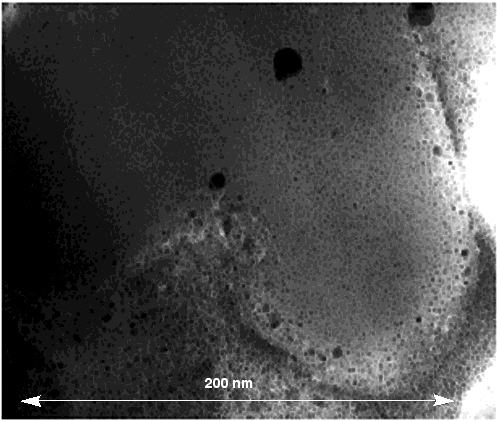
Figure 2. TEM characterization of a slice (thickness ~ 100 nm)
cut from a particle of Zeolite Y; Ru(bpy)32+ (22.9%);
TiO2 (27.2%) embedded in PMMA/graphite.
Electrochemical and Photophysical Measurements
Electrochemistry. The oxidation potential of the chloride salt
of Ru(bpy)32+, dissolved in (0.5 M Na2SO4) was measured to be 1.265 V vs SHE at a carbon paste/Au
grid electrode, a value consistent with those reported by others using conventional
electrodes. As shown in Table 2, when the complex
is entrapped within the zeolite structure, there is a slight shift in the
oxidation potential to 1.276 V vs SHE. This finding is not consistent with
the previously reported stabilization of the oxidized form of the complex,
Ru(bpy)33+, by the zeolite superstructure. This effect
is well established, resulting in cathodic shifts of the redox potentials
of many zeolite-encapsulated metal complexes. However, our preparation methods
of Ru(bpy)32+- doped and especially of our novel Ru(bpy)32+/ TiO2 - codoped zeolite Y materials
are distinctly different from the previously reported procedures (see above)
and lead to significantly higher Ru(bpy)32+-contents
and purities inside the zeolite's supercages. In addition, the doping procedure
of the zeolites with titanium dioxide using TiCl3 as
titanium source leads to an excess of protons in the interior of the zeolite´s
framework. Therefore, the cathodic shifts, reported in the literature, are
not apparent in our electrochemical experiments. The electrochemical redox
potentials measuered by differential pulse voltammetry (DPV) are summarized
in Table 2. Only redox potentials obtained for
the first scan in the anodic direction of each electrochemical experiments
are reported. However, if the DPV experiments are repeated several times,
a systematic shift of the Ru(bpy)32+/3+
redox potentials at high Ru(bpy)32+/3+
loadings occured. At the same time, the magnitudes of the electrochemical
signals are diminishing consecutively, At a redox potential of approximately
1.24 V, the investigated sample, which was highly loaded with TiO2
(37.1 %), was reduced to 50 percent of its original peak height. This behavior
is consistent with the work reported by Ganesan and Ramaraj , who also found
that the zeolite Y framework does not support electron transfer processes
between Ru(bpy)2+ metal complexes synthesized in its
interior, if the zeolite was immersed into aqueous 0.1 M Na2SO4. However, if protons were provided by employing 0.05 M
H2SO4 as electrolyte solution,
intense extra zeolite electron transfer between Ru(bpy)2+
was observed. On the basis of those findings, we interpret our results as
follows: In the beginning of the DPV-experiments, residual traces of protons
are present within the zeolite Y frameworks. Therefore, the typical cathodic
shifts of the Ru(bpy)2+/3+ redox
potentials were not detected during the first DPV scans. The following systematic
cathodic shifts down to 1.24 V (and even further) can be interpreted by
the loss of intrazeolite protons due to the leaching process into the bulk
electrolyte. Finally, the proton concentration inside the doped and codoped
zeolite Y becomes too low to mediate extra zeolite electron transfer processes.
Consequently, the electrochemical waves of the Ru(bpy)2+/3+ redox systems converge to zero. 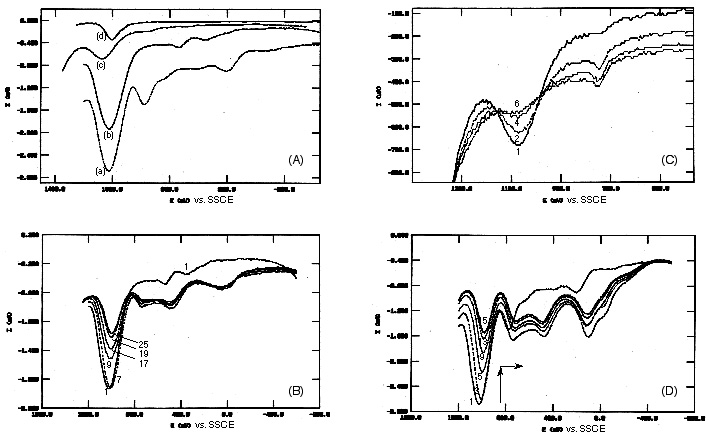
An explanation for the reversible electron transfer of Ru(bpy)32+ in the presence of a high metal complex content in the presence as well as the absence TiO2 within the zeolites framework is the supramolecular interaction of Ru(II) complexes. Since the Ru(bpy)32+ loadings explored are near one complex per supercage in those cases (Table 1) and two complexes do not fit within the same supercage, then the observed coupling between Ru(II) complexes would arise from intercavity interactions. In several examples of stongly coupled metal-metal systems indeed a anodic and/or cathodic shift of the oxidation potentials is observed relative to the monomeric analogs, usually accompanied by a an intervalence absorption band in the near-IR. This behavior could be explained by the interaction of coupled redox centers, which lead to the broadening of the electrochemical waves and therefore to a shift of the corresponding redox potentials.
Figure 3. Overlay of differential pulse voltammograms (DPV, +50 mV pulse height, scan rate: 10 mV s-1). The measurements were recorded immediately after immersion of the working electrode into 0.50 M Na2SO4 in water. The numbers of the showed runs are indicated in the figures.
(A) DPV measurements, first scans in the anodic direction of each electrochemical experiments are reported. (a) zeolite Y containing 23.3 % (weight percent) of Ru(bpy)32+ and 0% of TiO2. (b) zeolite Y containing 22.1 % (weight percent) of Ru(bpy)32+ and 37.1% of TiO2. (c) zeolite Y containing 10.8% (weight percent) of Ru(bpy)32+ and 9.4% of TiO2. Experiments (a)-(c) were performed employing a mixture of 200 mg carbon paste (Metrohm) and 100 mg of doped or codoped zeolite powder, pressed on both sides of a 15 mm x 15 mm gold grid as working electrode. (d) Ru(bpy)32+ in 0.50 M Na2SO4 in water using a 15 mm x 30 mm gold grid/carbon paste/zeolite Y as working electrode.
(B) DPV - measurements of zeolite Y containing 23.3 % (weight percent) of Ru(bpy)32+ and 0% of TiO2. The first 8 scans each in the anodic as well as the cathodic direction resulted in stable signals, a consecutive decrease of the DPV-signals is found starting with scan #9.
(C) DPV - measurements of zeolite Y containing 10.8% (weight percent) of Ru(bpy)32+ and 9.4% of TiO2. The recorded signals decrease beginning from the first scan consecutively.
(D) DPV - measurements of zeolite Y containing 22.1 % (weight percent) of Ru(bpy)32+ and 37.1% of TiO2. The recorded signals decrease beginning from the first scan consecutively.
Electronic Absorption and Emission. The diffuse reflectance spectra of zeolite Y prior to reaction, Ru(bpy)32+ doped, and Ru(bpy)32+/TiO2-codoped zeolite Y are shown in Figure 4. As expected, no absorption in the 350 nm to 800 nm region is observed in the absence of metal complex and TiO2 (Figure 4a). The characteristic MLCT absorption of Ru(bpy)32+ from 400 nm to 500 nm is observed in the Ru(bpy)32+ doped zeolite samples (Figure 4b) with a maximum at 460 nm. This MLCT absorption maximum is red shifted by 8 nm from that of Ru(bpy)32+ in water, consistent with the shift in redox potential of the Ru(III/II) couple within the zeolite. It should be noted that the absorption spectra of the Ru(bpy)32+ doped zeolites prepared by the method described here exhibit lower absorption at 530 nm, which corresponds to Ru(bpy)2Cl2, compared to spectra of samples prepared by the dry method.
It can be seen in Figure 4c that in the co-doped Ru(bpy)32+/TiO2 samples the absorption extends into the near IR. Since TiO2 itself does not absorb in the visible or near IR regions of the spectrum, it may be concluded that there must be some interaction between the Ru(bpy)32+ complexes encapsulated within the supercages and the TiO2 nanoparticles located at the windows. Additional evidence of this interaction stems from the red shift of the absorption maximum of Ru(bpy)32+ to 478 nm and the increased absorption of the Ru(bpy)32+/TiO2 systems throughout the 350 nm to 800 nm range relative to that in the absence of TiO2.
Although direct comparisons between the absorption and electrochemical results are desirable, the diffuse reflectance experiments only have a penetration depth of ~10 mm (from photoacoustic measurements). In addition, we believe that the concentration of TiO2 is greater near the surface than deeper within the zeolite particles, which are rectangular boxes with approximate dimensions of 1.0 x 0.5 x 0.5 mm.
The steady state luminescence of Ru(bpy)32+-doped
zeolite samples is also red shifted (lem ~ 630 nm) 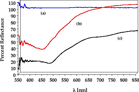 compared
to that of the complex in solution (lem ~ 610 nm). This behavior is in agreement
with earlier findings. The emission maximum further shifts to 645 nm in
the Ru(bpy)32+/TiO2-codoped systems,
consistent with a Ru(bpy)32+-TiO2
interaction. Owing to the limited light penetration and TiO2
concentration gradient within the zeolite, quantitative comparisons are
not possible.
compared
to that of the complex in solution (lem ~ 610 nm). This behavior is in agreement
with earlier findings. The emission maximum further shifts to 645 nm in
the Ru(bpy)32+/TiO2-codoped systems,
consistent with a Ru(bpy)32+-TiO2
interaction. Owing to the limited light penetration and TiO2
concentration gradient within the zeolite, quantitative comparisons are
not possible.
Figure 4. Diffuse reflectance spectra of (a): zeolite Y (Ru(bpy)32+ (0%); TiO2 (0%)) (b) Ru(bpy)32+ doped zeolite Y (Ru(bpy)32+ (23.3%); TiO2 (0%)) and (c) Ru(bpy)32+/TiO2-codoped zeolite Y Zeolite Y; (Ru(bpy)32+ (22.9%); TiO2 (27.2%))
Emission Lifetimes. The lifetimes of Ru(bpy)32+-doped zeolite Y differ both with Ru(bpy)32+ loading and TiO2 content. The lifetimes and pre-exponential factors of various Ru(bpy)32+-zeolite samples fit to a biexponential decay are listed in Table 2. The lifetimes and their corresponding contribution to the emission in the absence of TiO2 show a decrease of the lifetime of the long-lived component and its relative intensity as Ru(bpy)32+ loading increases. The biexponential decay of Ru(bpy)32+ encapsulated within the zeolite-Y supercages has been previously reported and discussed in detail, where the two lifetime components were attributed to complexes residing in different locations within the zeolite supercages.
In codoped Ru(bpy)32+/TiO2 zeolite Y the observed decay is dependent on TiO2 loading (Table 2). At low TiO2 concentrations the decay remains biexponential. However, above 27% TiO2 loading the emission lifetime becomes monoexponential, and increases with TiO2 concentration. Although this finding may initially seem counterintuitive since TiO2 is known to quench the Ru(bpy)32+ excited state, the observed emission stems only from Ru(II) complexes that are not in proximity to TiO2. Steady-state experiments show that those Ru(bpy)32+ complexes located near TiO2 within the zeolite do not emit light, since the emission intensity decreases dramatically while the lifetime remains constant or increases with added TiO2. These observations are consistent with static quenching being the only operative quenching mechanism of the Ru(bpy)32+ excited state by TiO2. The increase in the lifetime observed as more TiO2 is added to the zeolite is due to the presence of less accessible space in the supercages, resulting in lower Ru(bpy)32+ mobility.
Quenching by External Co(dpphen)33+. The emission of *Ru(bpy)32+ encapsulated within the zeolite supercages is statically quenched by Co(dpphen)33+ (E0Co2+/3+ = + 0.33 V vs. SHE) in the exterior of the particles. As the Co(dpphen)33+ concentration is increased the relative emission intensity of the Ru(II) complex decreases and finally reaches a plateau (Figure 5). From this behavior we conclude that only the Ru(bpy)32+ molecules residing near the zeolite's surface are quenched by the Co(III) complex. This observation is consistent with previous reports. Since a short lifetime component due to quenched Ru(bpy)32+ is not observed within the 500 ps time resolution of the single-photon counting instrument, it may be concluded that the electron transfer rate constant from *Ru(bpy)32+ trapped near the zeolite's surface to Co(dpphen)33+ is very fast (>1010 s1). Such static quenching from Ru(bpy)32+ entrapped near the surface is expected, since the surface of zeolite Y is negatively charged at pH ~ 7.8, resulting in electrostatic binding by the cationic Co(dpphen)33+ to the exterior of the particles.
The relative emission intensity quenching by external Co(dpphen)33+ for similar Ru(bpy)32+ loadings
(2223%) with increasing TiO2 content is also shown
in Figure 5. In addition, the values of Io/I in the absence and the presence
of 200 mM Co(dpphen)33+ for each sample relative to
that without TiO2 are listed in Table
3. It is clear that addition of TiO2 alone increases
the quenching of the emission intensity of Ru(bpy)32+
entrapped within the zeolite supercages, and further decrease in the luminescence
is observed upon addition of Co(dpphen)33+ (Table 3). It is evident from the calculated and observed
values in Table 3 that the quenching meaured when
both TiO2 and Co(dpphen)33+ are
present is greater than that calculated assuming that each component quenches
the Ru(bpy)32+ emission independently from the other.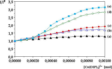
Figure 5. Relative emission intensity quenching by external Co(dpphen)33+ for similar Ru(bpy)32+ loadings (2223%) with increasing TiO2 content.
(a) Ru(bpy)32+ doped zeolite Y (Ru(bpy)32+ (23.3%); TiO2 (0%))
(b) Ru(bpy)32+/TiO2-codoped zeolite Y Zeolite Y; (Ru(bpy)32+ (23.2%); TiO2 (17.3%))
(c) Ru(bpy)32+/TiO2-codoped zeolite Y Zeolite Y; (Ru(bpy)32+ (22.9%); TiO2 (27.2%))
(d) Ru(bpy)32+/TiO2-codoped zeolite Y Zeolite Y; (Ru(bpy)32+ (22.5%); TiO2 (31.8%))
(e) Ru(bpy)32+/TiO2-codoped
zeolite Y Zeolite Y; (Ru(bpy)32+ (22.1%); TiO2 (37.1%))
It may be concluded from these results that a greater fraction of the Ru(II) complexes is being quenched by a given concentration of Co(dpphen)33+ in the exterior of the zeolite in the presence of TiO2. This conclusion is consistent with the facilitation of electron transfer from Ru(bpy)32+ in the interior of the zeolite to Co(dppphen)33+ at the surface by encapsulated TiO2. This increase in the electron transfer rate with TiO2 loading may be explained by the intervening TiO2 nanoparticles providing a better coupling between donor and acceptor or acting as a direct electron relay. This explanation is consistent with the observed shifts in the redox potential, absorption, and emission of encapsulated Ru(bpy)32+ in the presence of TiO2 within the zeolite, clearly indicating a strong interaction between the which provides a communication pathway for Ru(bpy)32+ molecules residing in adjacent supercages.
Conclusion
The synthesis and characterization of a novel heterogeneous photocatalyst is reported. The catalyst consists of the sensitizer Ru(bpy)32+ embedded in the cavity of zeolite Y in direct proximity to amorphous TiO2-nanoparticles. The photophysical and electrochemical properties of *Ru(bpy)32+ within the zeolite supercages were investigated. The photoexcited MLCT state of the zeolite-entrapped Ru(bpy)32+ reacts via electron transfer with Co(dpphen)33+ in the exterior of the zeolite particles. The relative quenching of Ru(bpy)32+ by external Co(dpphen)33+ increases as the TiO2 content within the zeolite is increased, where electron transfer from *Ru(bpy)32+ complexes within the interior of the zeolite are able to transfer electrons to external Co(dpphen)33+. This observation indicates that electrons can be transferred from the interior of the zeolite to the surface in the presence of an appropriate electron relay, such as TiO2 nanoparticles. This finding is of significant importance for the development of highly efficient AOT catalysts.
Acknowledgments
The authors are grateful to the NATO (CRG 971178), the Foundation of the German Chemical Industry (Fonds der Deutschen Chemischen Industrie: FCI) and the German Research Council (Deutsche Forschungsgemeinschaft BO 1060/3-1) for the financial support of the scientific collaboration. C. T. thanks the National Science Foundation (CHE-9733000) and The Arnold and Mabel Beckman Foundation for a Young Investigator Award for partial support of this work.
References